Bluebird 2
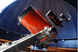
The primary equipment in the 10-foot dome is linked to a 14-inch telescope with an OEM mount. The tube is a Celestron C14 of early vintage. It was mounted into an engineered fork by a university engineering task force whose direction was geared to visual observing on a tour of communities and schools. To that end it was built to be pushed in any direction easily, then allowed to track with a synchronous motor. At the end of the task the equipment was surplussed and, subsequently, passed through several hands, finally ending up in my dome.
The Mount
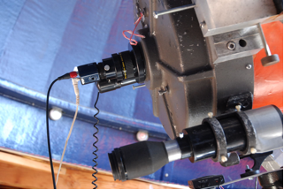
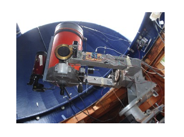
The fork is built around 4x4-inch aluminum tubing which permits easy attachment of mechanical and electronic modifications. The movement in RA is achieved by pushing against a slipping clutch and, upon stopping, by a 0.5 rpm synchronous clock motor. Additional fine motions in RA and DEC may be made by relatively slow stepping motors A wide range of visual and electronic devices is available. In the top figure above, the 14-inch mirror is monitored by a sensitive, 30 fps, video camera used primarily for the observation of occultations.
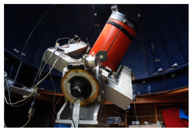
The open construction allows project work without interfering with the main driving functions. Major projects to date are:
- addition of encoders on RA and DEC,
- substitution of stepper motors on RA and DEC in place of the higher speed slewing motors,
- addition of Arduino microcomputing stepper-motor control.
Imaging Hardware
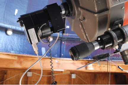
Two SBIG, ST-8 cameras are available. The first and oldest has parallel port connection to a computer. It is slower in download than the second which has USB data transmission. Each is otherwise interchangeable. Figure 3 shows the ST-8 with USB connection fitted, first, with a color wheel containing RGB filters, a diffraction grating, and a neutral density filter. An AO-8 adaptive optics unit is located in the first position in the stack.
The AO-8 is, basically, a 2-dimensional, transmission, flip plate which allows locking onto a star and tracking the sky while compensating for small fluctuations in position or, in the case of a bright tracking star, high speed corrections for atmospheric flutter. This mode of operation has resulted in the highest resolution images among those collected by the several modes.